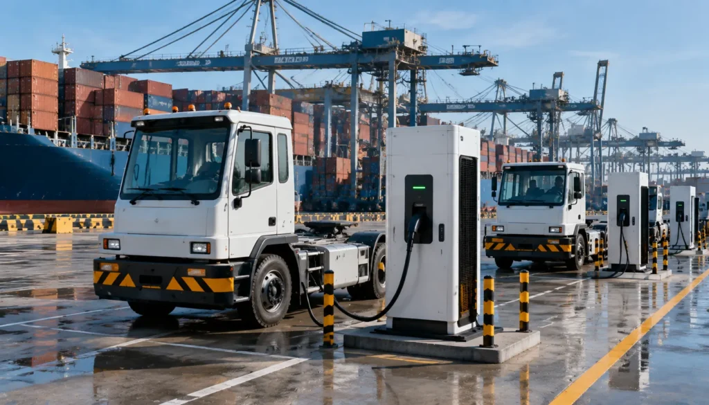
High Power DC Fast Charging Solution from 480kW to 800kW
Advanced liquid cooling technology for ultra-fast EV charging, delivering reliable 480kW-800kW charging solutions for global markets.
What is a liquid-cooled EV charger
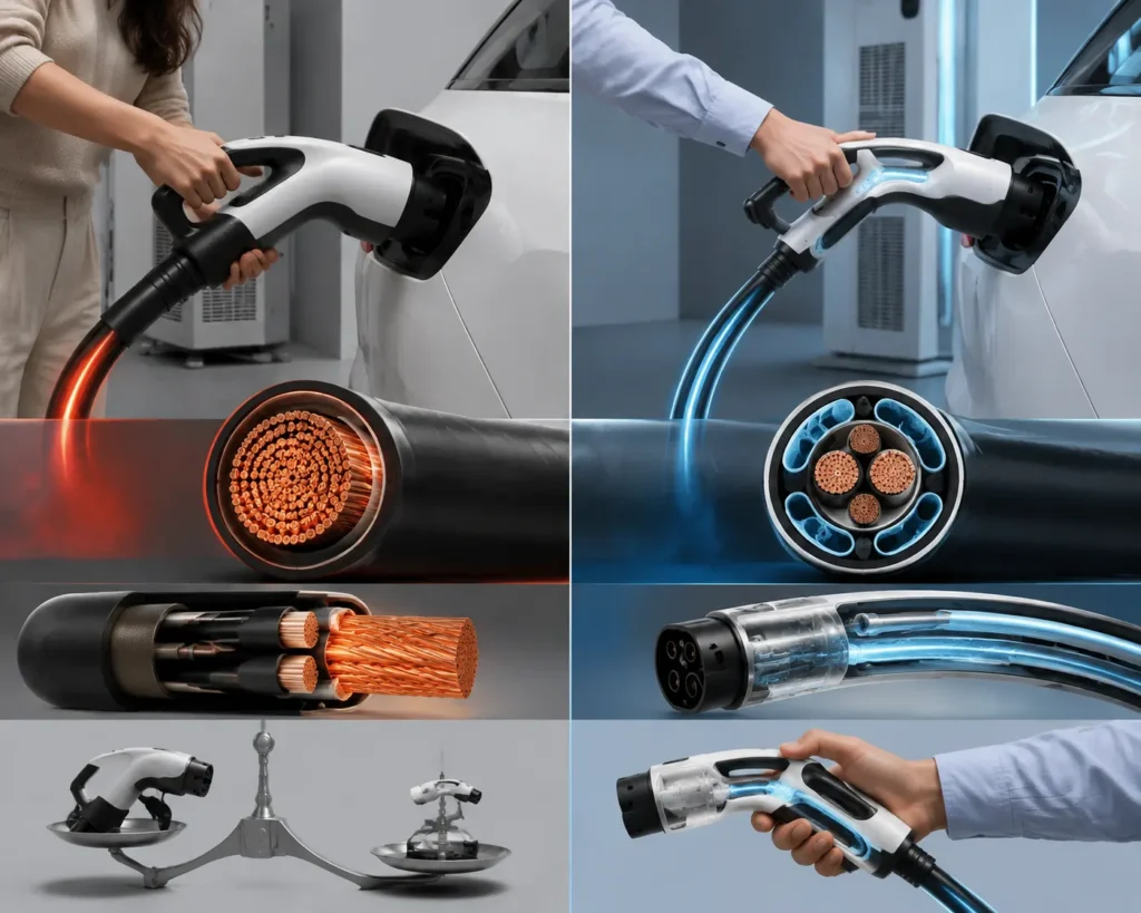
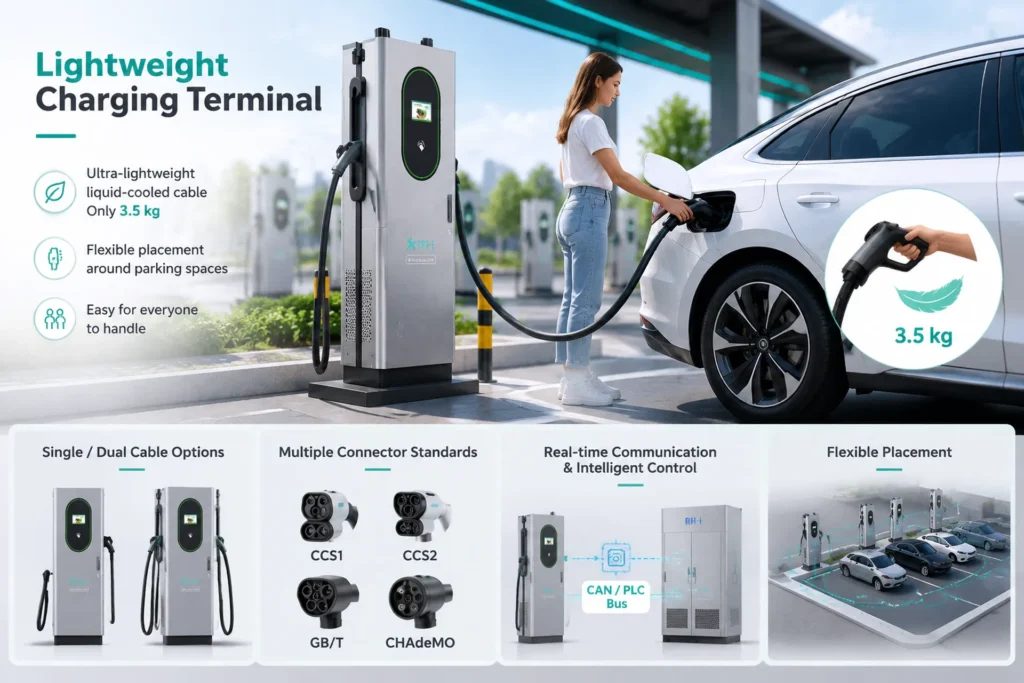
For a traditional charger, the greater the power, the greater the current, and the more severe the cable heating. For safety, the cable must be made very thick (with a heavy copper core), resulting in a very heavy charging gun, which is difficult for women or the elderly to operate.
Liquid cooling solution: Arrange small liquid cooling pipes inside the gun head and cable, and pass coolant (such as ethylene glycol aqueous solution or special oil) through them.
Effect: The heat is instantly taken away by the coolant, so the cable does not need to pile up thick copper cores. Even if the current is as high as 500A–800A, the gun cable can remain “cold,” and its weight is 30%–50% lighter than that of traditional fast charging guns, making it easy to operate with one hand.
Why use liquid cooling for EV chargers
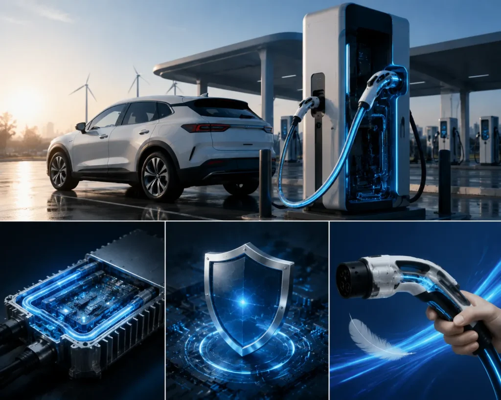
Liquid cooling technology is designed to break through the “heat dissipation bottleneck” of air cooling, so as to safely and continuously deliver ultra‑high power of 600 kW or more, while also making the charging gun lighter and more compact.
Key advantages include:
- Supports ultra-high-power charging
- Enhances charging stability
- Improves the charging experience
Liquid-cooled DC fast charging vs. traditional air-cooled DC fast charging
| Aspect | Traditional Air‑Cooled DC Fast Charger | Liquid‑Cooled DC Ultra‑Fast Charger |
|---|---|---|
| Cooling medium | Air (forced by fans) | Coolant (water‑glycol solution or insulating oil, circulated to carry away heat) |
| Charging cable & gun | Thick and heavy (relies on using more copper to dissipate heat, about 7–10 jin), hard to bend | Thin, soft, and lightweight (about 3–5 jin); the coolant carries away heat, so the copper core doesn’t need to be overly thick |
| Continuous power | Typically 60 kW – 250 kW; high power cannot be sustained for more than a few minutes (derates when overheated) | Generally 480 kW – 600 kW+; can sustain full power output continuously (liquid cooling keeps circulating to remove heat) |
| Noise level | Extremely loud (fans sound like a jet taking off at high power, about 75–85 dB) | Quiet (mainly just the sound of the water pump and slight fan noise, about 55–65 dB) |
| Equipment lifespan | Electronic components are baked at high temperatures for long periods, aging quickly (insulation typically becomes brittle in 5–8 years) | Operates in a constant‑temperature environment, extending component life and reducing failure rates |
| Maintenance cost | Low (but requires frequent dust cleaning and fan replacement) | High (requires maintenance of pumps, piping, and leak prevention, but less dust‑cleaning burden) |
| Application scenarios | Ordinary charging in residential areas and shopping districts (drivers have a meal and charge for 30+ minutes) | Highway service areas and major traffic corridors (drivers grab a coffee and leave after 15 minutes of charging) |
10+Years of Industry Experience
100+Countries & Regions Served
3000+ Charging Stations Deployed
50 kW-600 kW Power Range Flexible Configuration
24/7 Global Technical Support
Rectifier Cabinet Technical Parameter Table
| Model | RHAD480K-8-EU | RHAD600K-10-EU | RHAD720K-12-EU | RHAD800K-12-EU |
| Rated Power | 480kW | 600kW | 720kW | 800kW |
| Output circuit | 8 channels | 10 channels | 12 channels | 12 channels |
| Dimensions ( W×H×D mm ) | 1700×800×2100mm | |||
| Input voltage | AC400V±15% | |||
| Input Frequency | 50Hz±10% | |||
| Output Voltage Range | DC200~1000V | |||
| Maximum Output Current Per Channel | 250A-400A (optional) | |||
| Constant Power Output VoltageRange | DC300-1000V | |||
| Peak e翿 ciency | ≥95% (50%-100% full load output | |||
| Power factor | ≥0.99 (50%-100% full load output power) | |||
| Steady Voltage Accuracy | ≤±0.5% | |||
| Steady Current Accuracy | ±1% (output load range: 20%-100% ) | |||
| Current Imbalance Accuracy | ≤±5% | |||
| Ripple Peak-To-Peak | ≤1% | |||
| ITHD | ≤5% (50%-100%full load output power) | |||
| Insulation Resistance | ≥20MΩ | |||
| Noise | Ⅱ level | |||
| Cooling Method | Air blast cooling | |||
| Terminal Cabinet Communication | CAN communication | |||
| Mode IP Rating | IP54 | |||
| Operating Environment | Outdoor/Indoor | |||
| Operating Temperature | -40℃-50℃ | |||
| Storage Temperature | -40℃~+70℃ | |||
| Relative Humidity | 5%~95% | |||
| Altitude | ≤2000m | |||
| Installation Method | On-site installation | |||
Customize Your Smart Charger Now:
We offer a wide range of EV chargers, including over 200 models, and also provide customized solutions tailored to your specific needs.
The Core Solution for Large-Scale Charging Stations
Designed for EV charging hubs, fleet operations, and next-generation ultra-fast charging networks, our liquid cooling technology enables stable and efficient high-power charging from 480kW to 800kW.
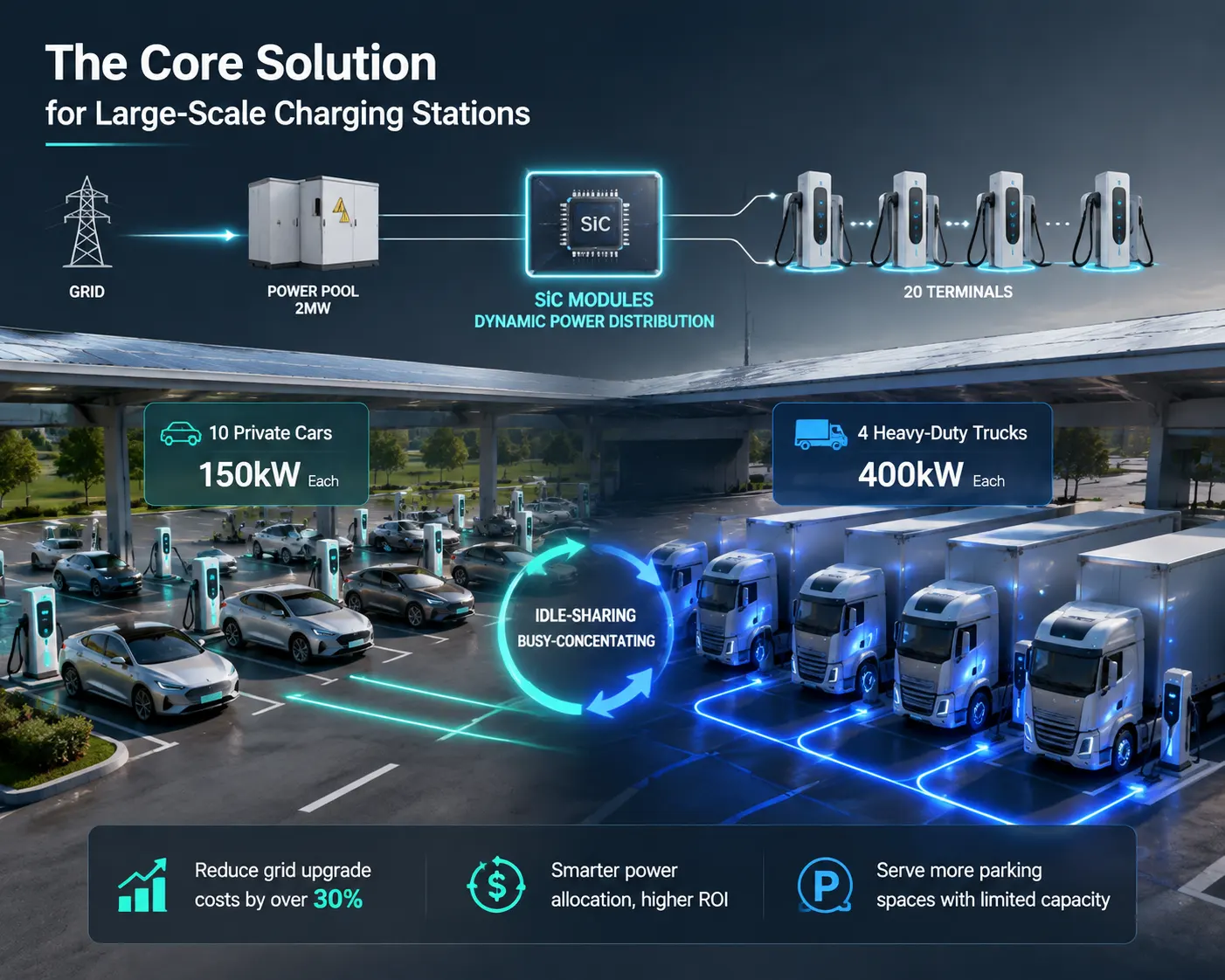
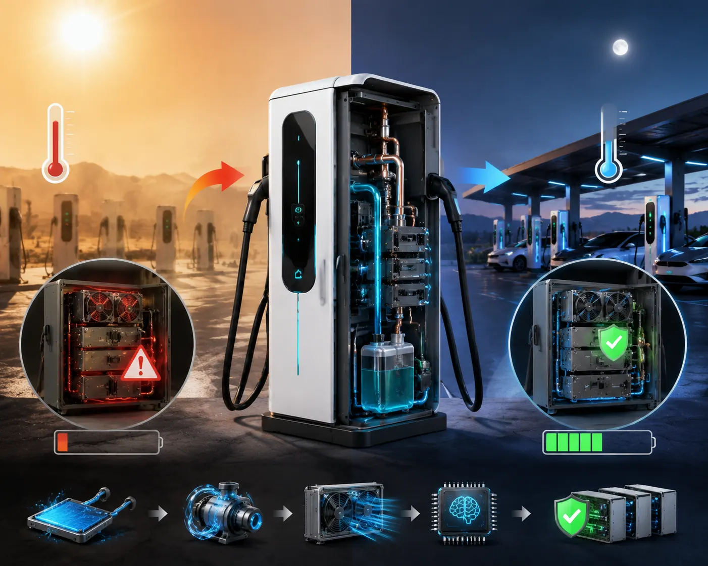
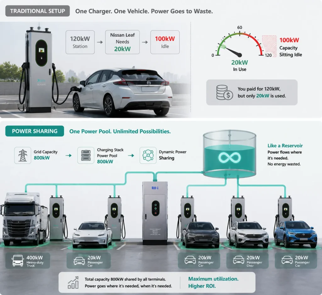
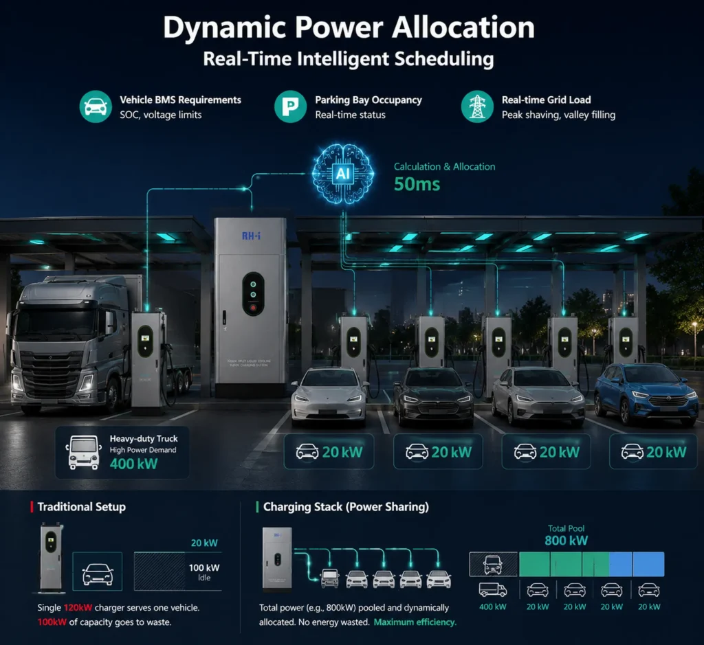
1. “Power Pooling” Architecture – The True Cost-Cutting Core
Dynamic flexible power distribution based on silicon carbide (SiC) modules.
Assume a total station power of 2MW supporting 20 terminals. The system does not allocate power statically; instead, it performs real-time “peak shaving and valley filling.” When 10 private cars are plugged in, each receives 150kW. If 4 heavy-duty trucks suddenly pull in, the system can “shift” power to the truck terminals within milliseconds, delivering 400kW each for direct charging.
This “idle-sharing, busy-concentrating” strategy helps customers reduce grid upgrade costs by over 30%, serving more parking spaces with limited capacity.
3. Integrated Solar-Storage-Charging and Demand Charge Management
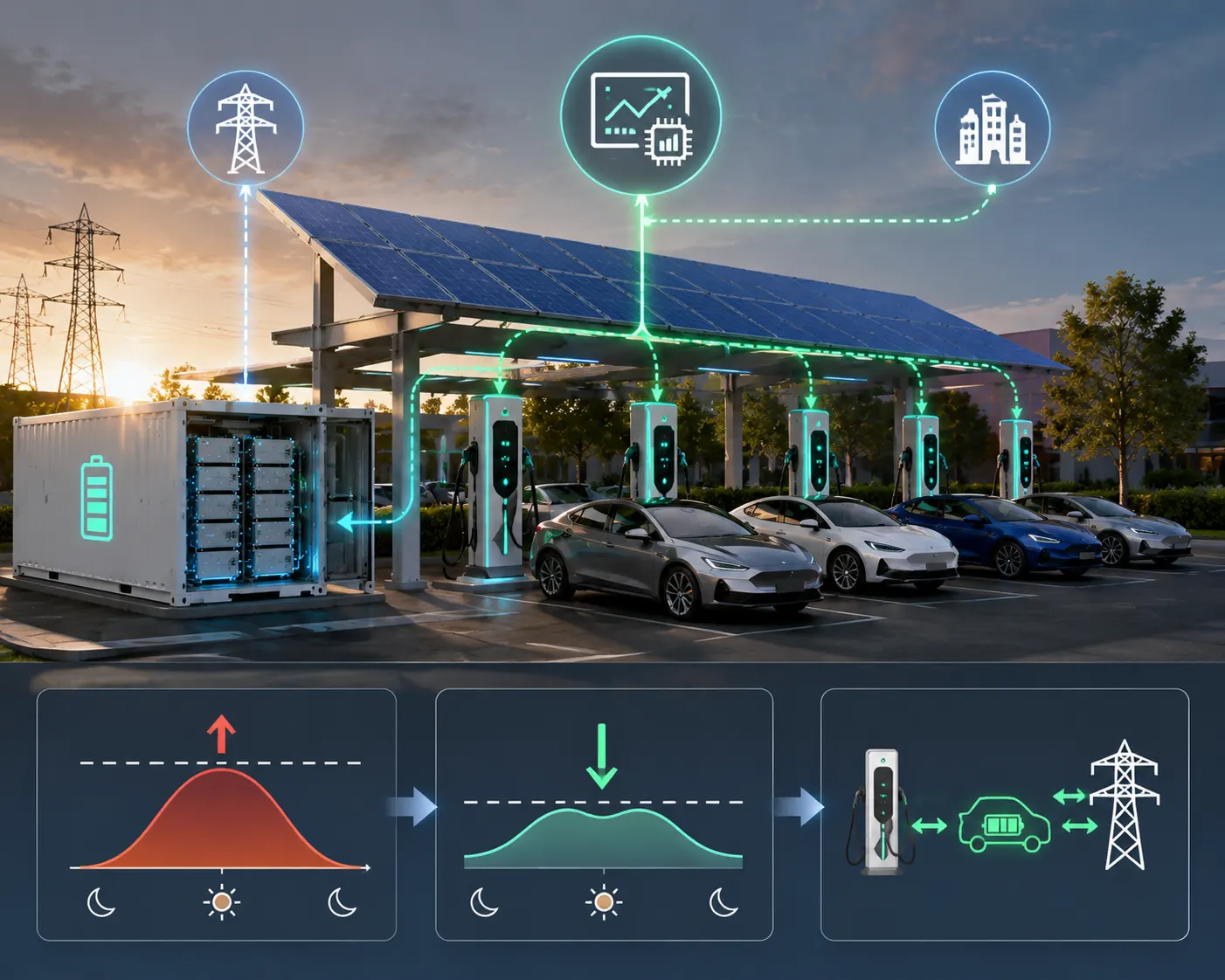
Deeply couple the charging system with local energy storage (BESS). Your EMS (Energy Management System) must feature demand‑charge peak shaving—automatically dispatching stored energy during grid peak load periods (such as 3 PM to 5 PM) to smooth out the site’s power draw from the grid.
The “base electricity charge” (based on demand) accounts for a very large portion of costs. This strategy can directly reduce the site’s fixed monthly electricity expenses by 30%–40%. Furthermore, with support for V2G (vehicle‑to‑grid) reverse discharge, it can participate in virtual power plant (VPP) demand response in the future.
Waterproof & Weather Resistant Design
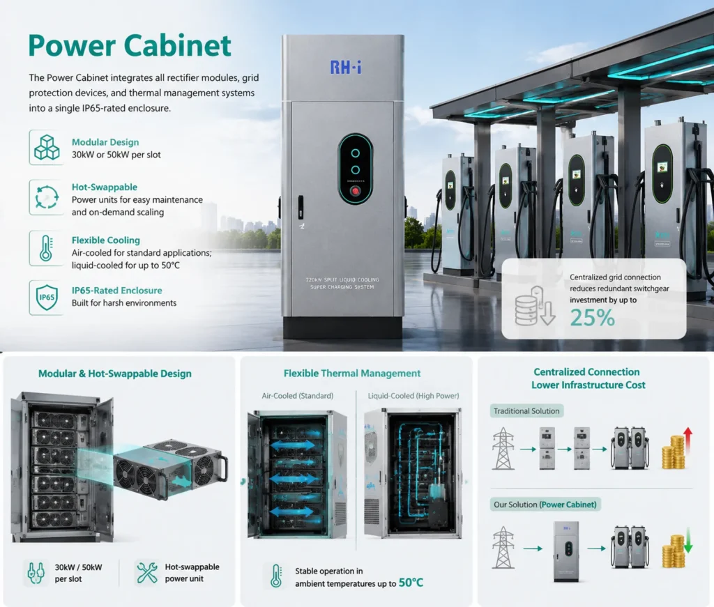
Before leaving the factory, every unit undergoes a cyclic aging test that includes spray, high‑temperature/high‑humidity, and low‑temperature condensation, simulating real‑world outdoor climate extremes. This validates the aging life of sealing materials and the airtightness margin of connectors.
The system strictly complies with IEC 60529 and has passed specialized verifications such as enhanced rain simulation, immersion testing, and thermal shock cycling. It covers demanding application sites ranging from highway trunk hubs and ports to mining operations.
Application scenarios
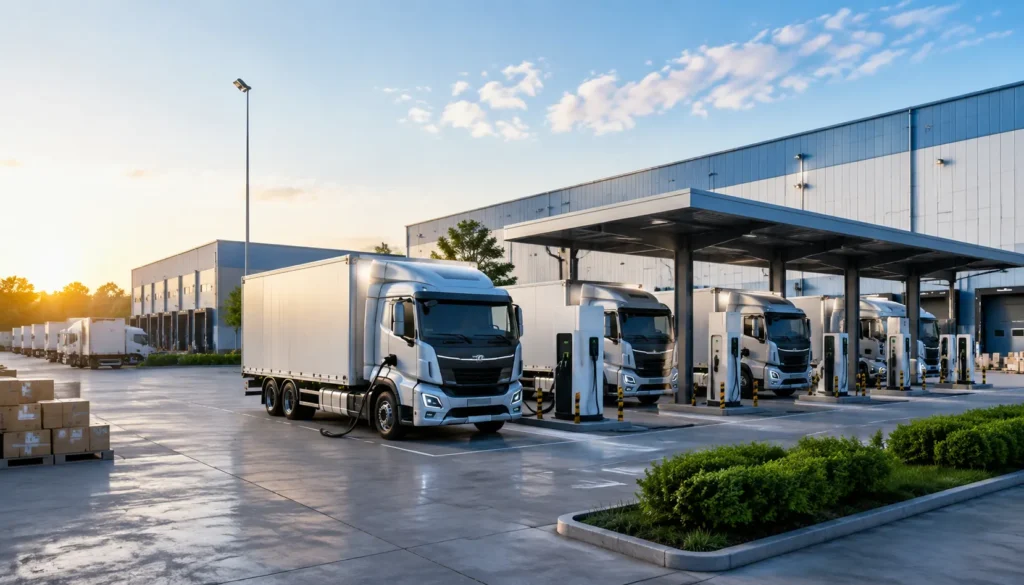
Logistics Fleet Charging
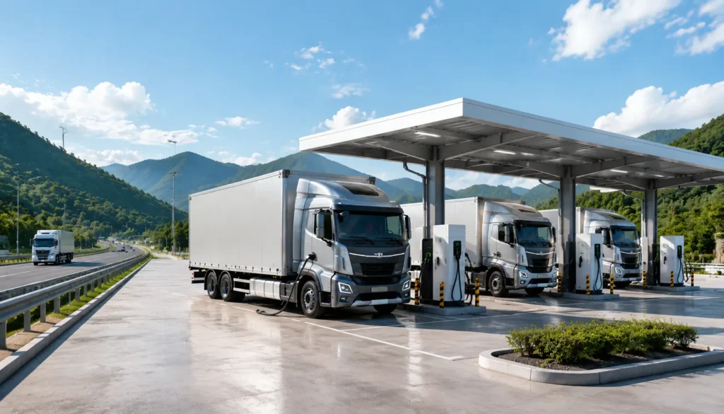
Highway Truck Charging Station
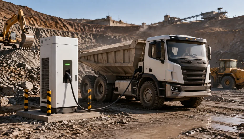
Mining & Construction Vehicle Charging